Showing posts with label How To. Show all posts

Friday, June 29, 2012

Outdoor Aerial Wire and Cable Installation - Moving Reel Method

Customers purchasing our many different types of outdoor wire and cable commonly ask how to lash cable to a messenger wire. One of the most common ways to do this is by using the moving reel method.


This method is used when reel carrying vehicles can drive most of the route. This method may be used when placing cable on a suspended strand or to an existing lashed cable and strand. Check out this cool lashing machine in action!


Each time a pole is reached the pulling stops. The cable guide (just in front of the lasher), and lasher get disconnected and moved past the pole. An expansion loop to the messenger is formed as temperature changes contracts the steel more then cables. Example below.


Before you get started let's go over some precautions.

* All personnel must be familiar with OSHA Occupational Safety and Hazard Act regulations.
* Follow the National Electrical Safety Code (NESC) for all installations.
* Cables installed near high voltage lines should be grounded.
* Cables that contain a corrugated steel tape should be grounded.
* The steel messenger shall be grounded.
* Make allowances for changing sag of the steel messenger wire in various weather conditions. Steel  messenger wire will expand and increase sag in warm weather.
* The steel messenger should be kept on one side of the poles (avoid zigzagging from one side of the pole to the other).
* Carefully inspect reels for imperfections such as broken flanges, cable crossovers, nails or anything that may cause damage as it is payed out.
* Follow the cable bend radius. Coax, phone and fiber wire and cable will differ.
* Never during the install should cable experience sags, bends and twist. A reduction in the cables transmission characteristics may not reveal itself till after installation.
* Do a pre-survey for splice locations, slack locations, cable storage requirements and possible obstructions like trees, roadways etc.
* You may want to consult an outside plant engineer.

As you can tell it sounds easy but lots of precautions do go into an installation of this type. I can hear my mother now, "Don't forget to put your helmet on!"

Thanks to Prysmian, OCC and Commscope.

"By Mercy Salinas"


Friday, September 9, 2011

How To Splice Fiber Optic Cable - Mechanical Splice

Instructions for splicing fiber optic cable with the AFL CS004162 mechanical splice kit. Watch quick overview video at bottom of post.

1.0 GENERAL
1.01 These instructions describe the operation of the SpliceConnect™ Universal Mechanical Splicing Tool. Please be sure to read these instructions carefully before proceeding.

WARNING: Always wear eye protection when handling optical fibers. Dispose of any cut or cleaved ends properly. Do not touch the wedge with bare hands.

1.02 The SpliceConnect™ CS004162 Universal Mechanical Splicing Tool Kit Contains:
• Mechanical Splicing Tool
• Instruction Manual
• Fiber Holder (900µm)
• Fiber Holder (250µm)
• Instructions Video (CD)
• Carrying Case

1.03 Tools and materials required:
• CT-30A Universal Cleaver (recommended)
• Fiber Prep Fluid
• Marking Pen
• Fiber Stripper
• Lint-free Cloth Wipes

2.0 INSTALLATION
2.01 Identify components of the kit. (see Figure 1)


2.02 Securely set the mechanical splice into the tool with the “F” logo upside down and on the left side. (see Figure 2)


2.03 Push the Red lever fully to engage the wedge into the splice. (see Figure 3)


2.04 Avoid damage to the fibers by making sure the fiber holder grooves and stripper are free of dust. (see Figure 4)

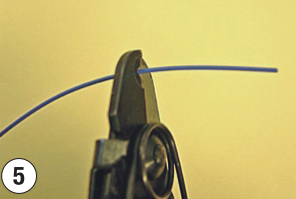
2.05 For 250µm: Mark 35mm from the end of the fiber. Strip the fiber to the mark. Clean the bare fiber. (see Figure 5)

For 900µm: Mark 35mm from the end of the fiber. Strip the fiber to the mark by removing 7mm at one time. Clean the bare fiber. (see Figure 5)


2.06 For 250µm: Place end of the fiber coating at the 10mm mark on the cleaver and cleave the bare fiber. The result is 10mm of bare fiber remaining after cleave. (see Figure 6)

For 900µm: Place end of the fiber coating at the 15mm mark on the cleaver and cleave the bare fiber. The result is 15mm of bare fiber remaining after cleave. (see Figure 6)


2.07 For 250µm: Set the fiber onto the holder with a protrusion of 25mm (10mm of bare fiber and 15mm of buffer coating). Gripping the front portion of the holder, slide the clamp downwards to lock the fiber. (see Figure 7)

For 900µm: Set the fiber onto the holder with a protrusion of 25mm (15mm of bare fiber and 10mm of buffer coating). (see Figure 7)


2.08 Set the fiber holder in the tool in line with the arrows on the rail. The fiber end should coincide with the tip of the fiber guide. (see Figures 8 and 9)


2.09 Slide the fiber holder forward until it is secured by the fiber holder lock. (see Figures 10 and 11)


2.10 Repeat steps 2.05 through 2.09 for the opposite fiber.

2.11 Insert opposite side of holder and fiber should bend on the side of the inserted holder. (see Figures 12 and 13)


(Except for 250µm to 900µm, the fiber on the opposite side of the inserted fiber holder should bend. (see Figure 14)


2.12 Press down the fiber bend and the opposite side should form a bend. (see Figures 15 and 16)


2.13 Balance the fiber bends on both sides. If the fiber bends cannot be balanced, restart the process with a new mechanical splice. (see Figures 17 and 18)


2.14 When the fiber bends on both sides are balanced, push the yellow lever to disengage the wedge. Fiber splice is completed. (see Figure 19)


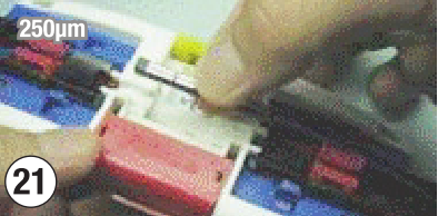
2.15 For 250µm: Release the fibers from the fiber holder by sliding the clamps towards the splice side. Make sure the fiber does not get caught by any part of the splice tool. Remove the splice gently. (see Figures 20 and 21)


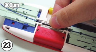
For 900µm: Release the fibers from fiber holders by opening the fiber holder covers. Make sure the fiber does not get caught by any part of the splice tool. Remove the splice gently. (see Figures 22 and 23)


2.16 Slide the fiber holder backwards and remove it from the lock. Do not keep the fiber holders locked in the tool. (see Figures 24 and 25)


Watch the mechanical splice video overview


Order all the fiber splice parts online at Discount-Low-Voltage.com:
AF-CS004162 mechanical splice connector kit
AF-CS004154 mechanical fiber splices
AF-CT-30 fiber cleaver
ID-45-350 fiber optic cable stripper
AF-FPF1 fiber optic cleaning solution

Friday, August 26, 2011

How to Make a Telephone Cable - DIY Video

To get started, let's make sure you have the necessary tools:


You'll Need:
RJ11/RJ45 Crimp Tool
Bulk Cat3/Cat5e Cable
RJ11 6P6C Modular Plugs
Electricians Scissors
RJ11/RJ45 Cable Tester

Now that we have all the right tools, let's make some telephone cables.

Step 1) Strip off about 1-2 inches of the cable jacket, being careful not to cut the individual strands of cable


Step 2) Separate all 4 pairs of cable


Step 3) Cut off the brown pair, and line up the cables using the USOC wiring diagram. We will be using conductors 2-7, since this is an RJ11 6P mod plug.


Step 4) Cut the cables as straight as possible, leaving around 1/4" of cables


Step 5) Insert the cable into the modular plug. Keep constant pressure on the cable, to assure the pairs do not come out of order. Make sure to press the cable all the way to the front of the mod plug.


Step 6) Insert the assembly into the 6P slot on your crimp tool, keeping pressure on the cable. By pushing slightly on the cable towards your tool, you will reduce the risk of the cables backing out slightly. Squeeze the tool all the way, remove the plug and repeat the same steps on the other side.


Tuesday, August 16, 2011

Is There Signal Loss Using Coax Cable TV Splitters?

So your installing a structured wiring system with coax cable and your wondering how much signal loss you'll get using coax splitters. If you have a handful of coaxial cable splitters, what's the best way to reduce your signal loss? Should you use multiple 2-way splitters, or a single 8-way splitter? Our good buddy Ron Kipper from Ideal Industries gives an excellent explanation of how much signal loss you can expect.


On a personal note, as a video gamer I had a constant problem with my internet signal dropping in the middle of a match on XBOX live. This is very irritating and a problem that shouldn't be happening. After a technician troubleshooted the problem, he replaced a 4 way splitter with a 2 way that was on the external part of the house. No problem ever since! Wish I viewed this video before.

For weekly videos, check out the Discount Low Voltage YouTube Channel and for more of Ron, check out his channel at Ron Kipper Data Comm YouTube Channel.

We hope you learned something. If you did, leave a comment for us below. Or ask us your questions in the comments box. Want to see something else? Suggest it below!

Related Posts:
How to Fish Wires Through a Wall or Ceiling
How to Crimp RG6 F-Connectors
How to Make an Ethernet Cat5e/Cat6 Cable
How It's Made: Low Voltage Cable

Friday, August 5, 2011

How To Terminate Cat6A Keystone Jacks - Video and Pictures

Cat6a keystone jacks and cat6a cabling are not much different than regular cat6 products, but do require a little extra attention to detail. The individual pairs in cat6a cable are twisted much tighter, and need to remain that way all the way up to the termination point. If the pairs are untwisted, you may not get your cable to pass the certification tester. In today's blog, we'll take you step-by-step through the process of terminating cat6a keystone jacks, using cat6a cabling. To get started, let's make sure you have the necessary tools:


You'll Need:
Cat6a Keystone Jacks
Cat6a Bulk Cable
Punch Down Tool
110 Blade for Punch Tool
Electricians Scissors
Keystone Jack Palm Puck (optional)

Now that we have all the right tools, let's terminate some cat6a jacks. 

Step 1) Strip off about 2-3 inches of the cable jacket


Step 2) Pull the 4 pairs of cable back, and remove the center divider (spline)


Step 3) Each Cat6a jack has the 568a and 568b wiring diagram chart on it. We will be using the most commonly used, 568b wiring diagram.


Step 4) Lace up all 4 pairs of cable on the cat6a jack, remembering to follow the 568b diagram


Step 5) Punch down wires onto keystone jack using the punch down tool and 110 blade. Make sure the side that says "Cut" on the 110 blade is pointing towards the outside of the cat6a jack.


Step 6) Put the dust cap cover on the cat6a jack and your done! It can now be inserted into wall plates, surface mount boxes or keystone patch panels.


Watch the video: How to Terminate Cat6A Keystone Jacks


Related Posts:
Video: How It's Made - Bulk Cat6, Cat5e, Cat3, and OSP Cable
Pictures: How to Terminate Cat6A Shielded Keystone Jacks
Crazy Data Center Wiring Pictures
UL Warning: Counterfeit Cat6 Communications Cable on the Market
UL Requires New Holographic Labels for Low Voltage Communications Cable

Thursday, August 5, 2010

How To Find Underground Wires & Valves Using Greenlee 521A


Contents:
1) Headset
2) Ground Stake
3) Transmitter
4) Receiver
5) Carrying Case
6) Black Lead
7) Red Lead
8) Selector Knob
9) ON/OFF Switch
10) Battery Cover

Batteries (included)
• Transmitter: Qty 8 - "D" batteries
• Receiver: Qty 1 - 9v alkaline battery

Note: The transmitter produces high voltage. Turn the transmitter off before handling the output leads. Disconnect all wires from the controller when fault locating. Turn the selector knob to the BATTERY TEST position. The meter should read between 8 and 10.

Before starting, you must ensure the transmitter is set up properly.

IMPORTANT: To ensure that the 521A transmitter is producing optimum signal, connect the red and black leads together and turn the unit on. Turn the selector knob to position #5. The meter needle should rise to at least a 10 reading.

1. With the transmitter off, connect the red lead to the wire to be located and the black lead to a good earth ground with the stake provided. (Refer to Figure 1). If the clock is indoors, the earth ground stake MUST be grounded at the point where the wires exit the building. It might require running a length of wire to the
outside. Do not use a common ground inside (i.e., electrical or water pipe).


2. Now turn the transmitter on and start rotating the selector knob clockwise.
Once you leave the BATTERY TEST position and go to #1, the meter needle will fall off to near zero. As you increase the output, the needle will rise slightly with each advancement. Stop when the meter reads between 4 and 8. The transmitter is now set for maximum efficiency for this job. If a reading of 4 is not obtainable, you may not have enough of a ground fault to locate the wire.

Soil condition can also affect the efficiency of the unit. Moisture is a good conductor, so the wetter the soil, the better. In dry or sandy conditions you may experience signal loss. Add some water near the ground stake to improve results.

3. Plug the headset into the receiver if desired, turn it on and point the antenna or probe end at the transmitter. A pulsing tone should be heard through the headset and an indication should register on the receiver meter.

Operation

Locating Wire Path
With the probe pointed toward the ground, walk completely around the transmitter location. An absence of tone or null will be detected directly over the path of the wire. Movement to either side will cause the volume of tone signal intensity to increase. Follow the null to determine the wire path. (Refer to Figure 2.)

Finding Wire Breaks and Nicks
When attempting to find breaks and nicks, you should decrease the sensitivity of the receiver when pointing it off to either side of the null. You will be able to notice the change in signal intensity immediately. Do not allow the meter to peg or go above 10. This will greatly help in the fault locating process.
Note: The wire must have a path to ground to be successfully located. These paths exist in a great majority of all direct buried wires due to insulation imperfections, nicks, and bad splices. If not, create one by grounding the remote end.
• The end of a cut or broken wire can be located by following the path until the null disappears and gives way to a hot spot. Beyond the hot spot, no null can be detected. Back up until the null is detected, and this will be the approximate end of the broken wire. (Refer to Figure 3.)
• Larger nicks in the wire can be located in almost the same way as locating opens. Follow the null and strong signal along the sides of the wire until the signal becomes very weak along the sides of the null. This will occur within a relatively short distance. The transmitted signal bleeds to ground at the nick and then wants to return to the ground stake along the outside of the wire itself. The majority of signals will stop at the nick indicated by the low receiver reading just beyond the nick. (Refer to Figure 4.)
• To more accurately define the location of an open or larger nick (ground fault), position the receiver tip on the ground near the point where the last strong signal was detected along the side of the path. The receiver tip should be pointing at the ground and be approximately 6 inches to either side from the null. Because you are so much closer to the path, the sensitivity knob must be adjusted down until the meter reads just below 10.

While maintaining the 6-inch distance from the null, move the receiver down the line, paying close attention to the meter reading. Once you pass the open or nick, the meter will fall off rapidly.


Determining Depth of Wire
To determine the depth of the wire, first mark the ground directly over the path. Turn the receiver sideways to the path, and tip it 45 degrees. Move the receiver away from the path, maintaining the 45-degree tip until a null is detected. Mark this spot. The depth is the distance between the two marks. (Refer to Figure 5.)


Two-Step Solenoid Valve Locating Process
Solenoid valves can easily be located provided all the wires leading to them are intact and the solenoid itself is still good.
Step 1. Start at the clock. Connect the red transmitter lead to the station wire leading to the subject valve, and connect the black lead to earth ground. Turn the transmitter on, adjust the output to the highest level, assemble the receiver, locate the path, and start tracing the wire following the null. The null will be present until you pass over a solenoid valve, and then the signal will become extremely strong. Mark this spot. Check around this hot spot for a null leaving the area. If the null continues, follow it and mark any additional hot spots. (Refer to Figure 6.) If only one hot spot or valve is located, it will be the valve in question.
Step 2. If more than one hot spot is found, mark them and return to the transmitter and turn it off. Lift the black lead from the ground stake and connect it to the common wire. Turn the transmitter on, set the selector knob to the highest reading, and return to the first hot spot with the receiver. Touch the tip of the receiver antenna to the ground in the center of the first hot spot and set the sensitivity knob to read near mid-scale. Now go to the second spot and without touching the sensitivity knob, check the strength of the signal at each hot spot and determine which, out of all of them, is the strongest signal. This is the valve for the station wire you are connected to.


Greenlee 521A Maintenance

Battery Replacement
1. Turn the unit off.
2. Remove the battery cover.
3. Replace the batteries (observe polarity).
4. Replace the battery cover.

Cleaning
Periodically wipe with a damp cloth and mild detergent; do not use abrasives or solvents.


Questions? Leave them below. Thanks!

Wednesday, May 19, 2010

How To View Security System DVR with Your Cell Phone - iPhone - Blackberry

In today's economy, theft is a rising concern for homeowners/business owners. According to the Federal Bureau of Investigation, there were an estimated 6.6 million (6,588,873) larceny-thefts nationwide in 2008. The loss to victims was nearly $6.1 billion. That's a $925 loss on average. Newer technology is helping us pave the way for a safer future, and cell phone's have played a crucial role. With advancements in DVR technology, it is now possible to view your security system remotely. Everfocus has introduced 2 new DVRs that support mobile viewing, the Paragon264 and ECOR264 series. Here's how you set up your DVR for mobile viewing:

1) The DVR must be accessible from the internet via the same process usually employed for DVR remote viewing:
     a. the DVR IP configuration must be consistent with the local network
     b. the router in the system must be configured to forward any traffic for the HTTP port used by the DVR to the IP address of the DVR. Please refer to the DVR User Guide for setting up the DVR network configuration.
2) In the Configuration Menu Network Setting Screen, the new option in the LAN setup "Enable Mobile Viewing" must be checked.

To view, launch the web browser on the mobile device or PC and enter the URL in the form:

http://ZZZ.ZZZ.ZZZ.ZZZ:PPPP/m/live.htm
or
http://dvrddnsname.everfocusddns.com/m/live.htm

where ZZZ.ZZZ.ZZZ.ZZZ is the IP address of the DVR
PPPP is the HTTP port used by the DVR
dvrddnsname is the DDNS name registered with the Everfocusddns.com server

You will be prompted for the login ID and password to access the DVR. Please remember that the ID is case sensitive and the password is numeric.

After entering the ID/Password, choose "OK" or "Log In" and you will see the live view screen. Click on a camera button to select that camera.


Everfocus H.264 DVR's are compatible with many different types of cell phones for remote viewing

Current Mobile Device Verified Compatibility *** (updated 8/3/10) ***

Apple iPhone on Safari
Apple iPhoneGS on Safari
Apple iPod Touch on Safari

T-Mobile/HTC Wing on Opera 10/Windows Mobil
T-Mobile/HTC MDA on Opera 10/Windows Mobil
T-Mobile/HTC HD2 on Opera 10/Windows Mobil
T-Mobile/HTC myTouch on Opera 10/Windows Mobil
T-Mobile/Google G1 on Included Browser

Motorola Droid on Included Browser
Motorola Droid X on Included Browser

Blackberry Bold on Included Browser
Blackberry Curve on Included Browser
Blackberry Tour on Included Browser
Blackberry 8220 on Included Browser
Blackberry 8300 on Included Browser
Blackberry 9000 on Included Browser

Samsung Jack on Opera Mobile 10/Windows Mobile 6.5

(Note: This may not be the complete list. This is just the ones we have verified that will work. If you have an older model DVR, you might be required to Upgrade Your Firmware for cell phone viewing on certain models.)

Related Posts:
Press Release - H.264 Compression Technology
Security Camera System Frames Per Second Comparison Video
How To Create a Low Budget CCTV System
Ideal SecuriTest Pro CCTV Camera Tester